Hello there, this is about swapping a k24 or k20 in a Crz. In this swap a k24a2/a3 is being swapped. Purpose to do a K24 swap is that it is a lot cheaper than k20 and has more torque and is at 200 Hp and has very much potential to go up in Hp range very easily, plus is boost friendly as it has 10.5:1 CR.
Until recently ( Nov 18,2017) HAsport only made mounts of K-swap(k20 only) for either Civic Si(k20z3) transmissions or DC5 ones which added to swap cost as they are very expensive. If you were to use a k24 block, you would still need a k20z3 or a K20 DC5/RSX-S transmissions. But now HAsport makes mounts for CRZ which support k24 transmissions (TSX 6 spd, Civic si 2012-2015).So now a complete k24 swap can be done in very less $$$$
Now presenting the video series which contains many new things,covers both k24 & k20 route.Also covers Zf1 & Zf2 aswell as Fit GE(2nd Gen) and Fit GK(3rd Gen).
Complete k swap guide part1
Estimated Project cost will be 4500-5000$.(Can go up depending upon labor of shop). This will be very feasible alternative to SC or Turbo kits available for Crz which cost from 3000-5000$
Costs:
Engine k24a2/a3 with 6 spd manual transmission 1500$-2000$
Shifter & cables= 150$ https://www.ebay.com/itm/2006-Honda-Civic-Si-Shifter-And-Shifter-Cables-OEM-K20z3-/282665373668?fits=Make:Honda|Model:Civic&hash=item41d02b4fe4:g:GeEAAOSwYyxZf5NL
HAsport Mounts for k24 (now they make them) 700$ (You have to mention k24 and its transmission type when placing order)
Flashpro/Ktuner: 700$/450$
Axles: 500$(HAsport crz for k24, tell them to ship the k24 ones as the k24 half shaft is longer than k20 )
Or you can buy Insane shaft axles which are rated for 500 hp ,I contacted them and they got data of axles from Hasport (Thanks Brian for sharing data for our sake).So now you can get those in 350$ instead of HAsport 500$ and more strong also than HAsport.
It has come into my information that stock k20z half shaft and axles are bolt ons. This engine comes in Civic Fd1(Malaysia) or you can search which alternate version internationally.
I have tried Insaneshaft axles in my Fit and both axles did't fit. So kindly contact Insaneshafts before buying that if axles dont fit they will return them back and refund you.
K20 idler pulley optional: 40$(If k24 have hydraulic Power Steering pump pulley and you don’t want to use that, just disconnected the hydraulic PS lines but keep the pump and pulley there for belt sake, will save you Idler pulley as well as new serpentine belt cost)).but will require a slight modification in power steering pump so that it doesn’t get jammed running without any oil in it.
Civic Si wiring: 120$
Si ECU+ Ignition key Optional =190$( not needed if you can tow your car to Honda dealership and match the new ECU with your old CRZ keys
Custom 2-2.5” exhaust=??
Headers OEM k24
Civic Si primary O2 sensor(Or you can use CRZ one,Yes it was done in a swap in Zf2 chassis in Malaysia and it worked) =120$
Secondary o2 sensor=Optional.
Radiator OEM (its more than enough, we have three k20,s and two 24 running with OEM crz radiators and are just fine, temperature remains 90-94 C.
Misc=IAT sensor, wiring grips (If you don’t want to use your Crz one’s)=50$,coolant 4L,oil etc
Spark plugs can use the ones that come with engine(k24 or k20,BKR7EIX) but I advise new: 35$
Tune: you can use any base TSX/Si map given in Flashpro calibrations
Honda dealership matching of your new immobilizer key and civic Si ecu=50$ ?
Intake: Can use that comes with new engine or just a short ram with K&N filter =50$
Cost:4600$
Swap shop labor if you don’t have engine stand=? 400-500$ ??(shops here cost 120$ for whole engine swap)
The purpose of this thread is to do almost all work as D.I.Y and at end if you don’t have engine stand to put the engine in/out than you can go to a shop to put engine in just in few hours.
As labor is not so cheap in some countries and they cost per hour bases, so purpose of this build is to get most work done before going to workshop for final engine swap.
Some of you may know me for my Honda Fit Hybrid k20 swap.
Here it is.
It had same LEA Mf6 engine of a CRZ and the wiring of it was copied from a k20 swap crz but was never documented in detail. To date the wiring of CRZ k20 is difficult but it is about to become real easy.
In Pakistan first k20 Crz wiring was done by electrician M.Anwar in 2013. It took him near 2 months to do so as at that time very little support was there about the swaps in modern OBDII cars, yet a hybrid. The fist CRZ was done using two ecu method. The OEM k20a ecu using kpro and a crz ecu.
2nd crz was done by using single ecu of Civic Si USA(2007-11). This method is superior as it has functional OBDII port and the gauge cluster, ABS etc works. Still no documentation was done.
3rd was my car.
here is the thread about its swap
Although I wanted to document the wiring in detail in that build but I failed to do so because it was really complex and i was a beginner in this field.
At that time I promised to myself that I will document it so that its easy enough to do as D.I.Y and the one doing swap is prepared for what is required and what problems he will/might face, like AC compressor hitting chassis and break booster hitting the engine, Radiator fans hitting the intake manifold etc. If you have an automatic CRZ than don’t worry either because I will document all the method from CVT to a manual conversion and it very easy because even in a manual crz you will have to use the new shifter of civic si/tsx and cables. so only thing remains for a cvt is to add a used clutch paddle from a Honda CRZ/Fit/jazz/City/Civic along with its respective cylinder. Conversion will not cost more than 200-300$.
So with no further delay lets start
In the name of Allah, the Most Gracious, the Most Merciful
English is not my language so I apologize for any spelling and grammar mistakes.
Special thanks to Mr.Anwar and Ustad Danish who helped me when I needed.
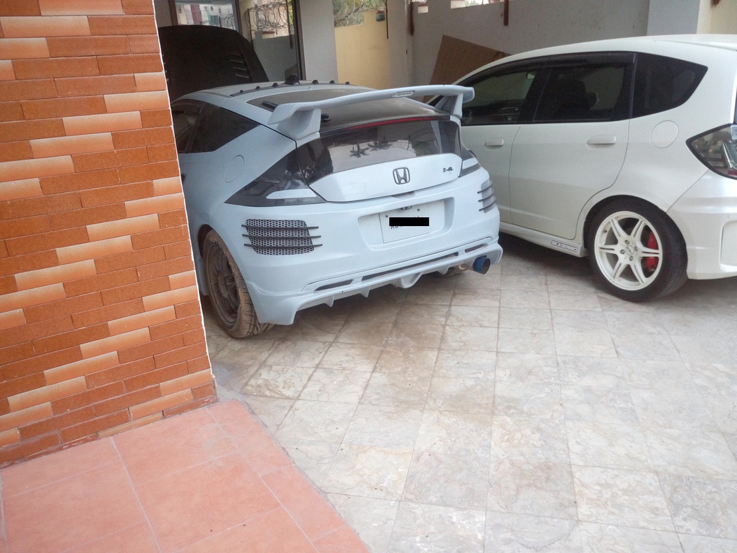
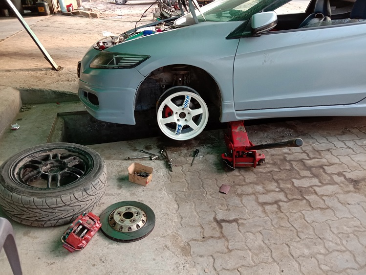
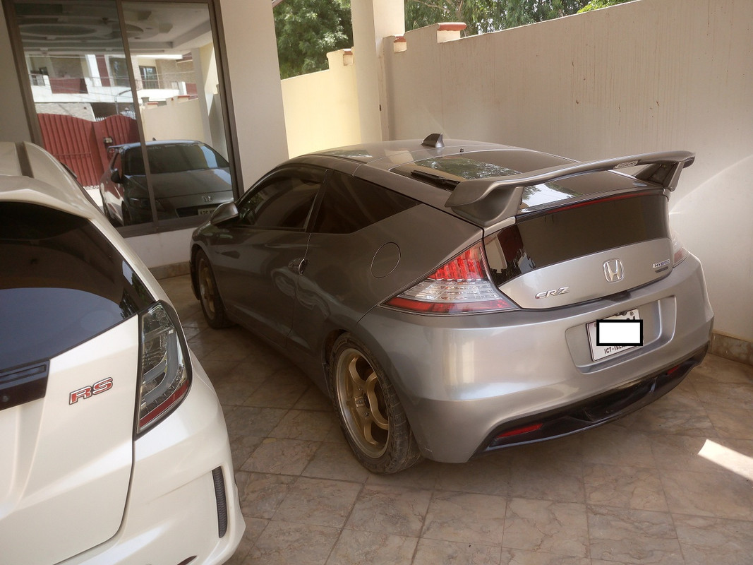
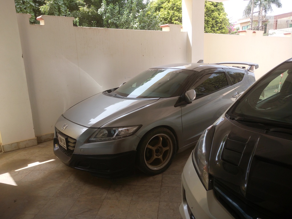
Here is crz I bought recently for the project. Its a 2010 MT.
![Image]()
![Image]()
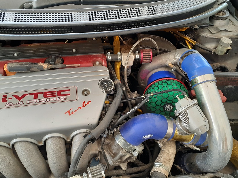
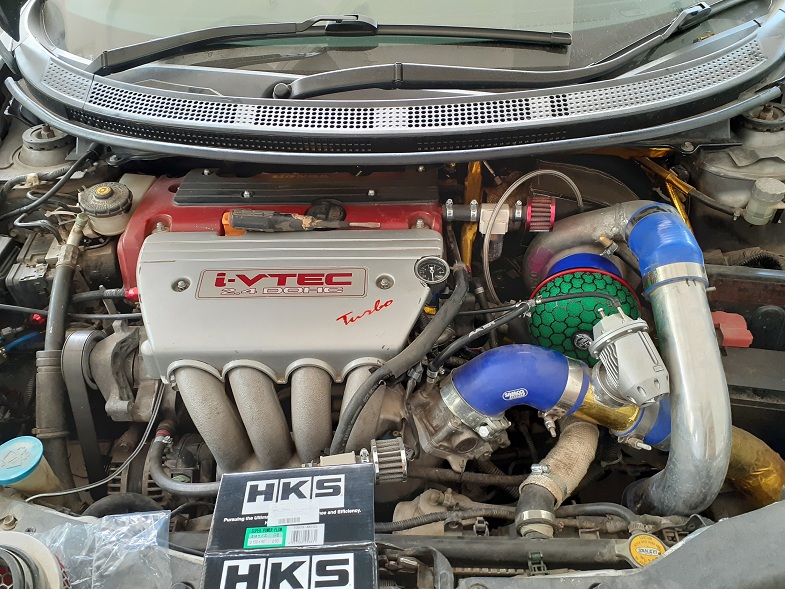
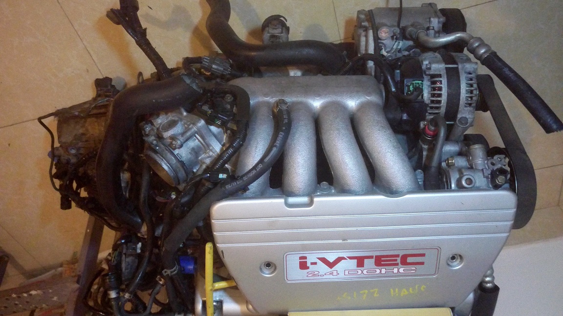
Here is the k24 engine for swap
![Image]()
![Image]()
This thread will mainly focus on doing all the work prior to engine installation into engine bay. Goal is to swap k20/24 in just few hours.
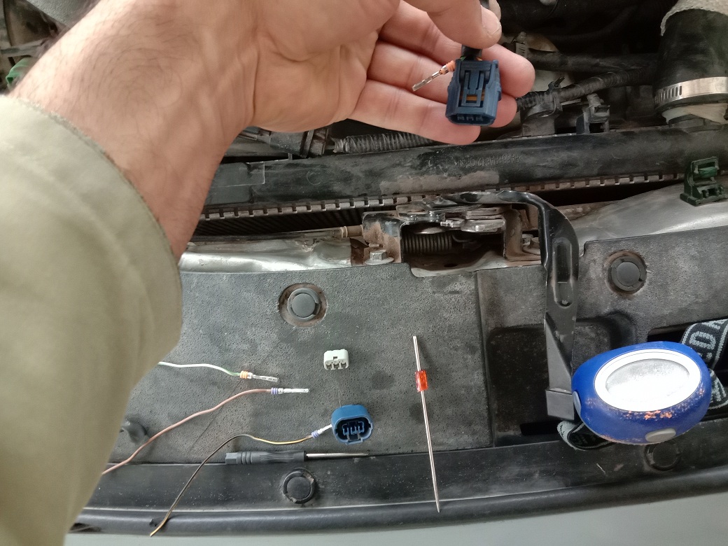
There are some sensor grips and main wiring grip you need to buy. Its better if you have a junk yard nearby. If you want to use a k24, than you will have to change oil pressure sending unit, Knock sensor grip, Crank sensor grip.(All these can be used of your Crz engine, but if you plan to return your crz to stock in future and don’t want to use any of its parts than you will have to find these from a junkyard or ebay etc). You will need IAT sensor and its grip.(The crz uses MAF sensor which has IAT sensor integrated into it ,so you will have to buy it, I will give its details in sensor wiring section)
As JDM models don’t have Hill assist so at this time we don’t know if it poses any problem in a k20 swap crz which has it.
I will cover each section of build separately but emphasizing most on how to do wiring on your own.
Here are the link to quick navigate to the pages..
Sensors sweap and sensors wiring connectors modification and engine preperation depending upon engine Page 1
The new forum format has changed the page numbering so much.
Break booster,oil pump,HAsport mounts and instructions Page 2
Engine preperation,clutch,flywheel installation etc etc Page 3
Alternator and starter wiring,immoblizer,pinouts etc Page 4
Main wiring,vss wiring,O2 sensor wiring etc etc Page 5
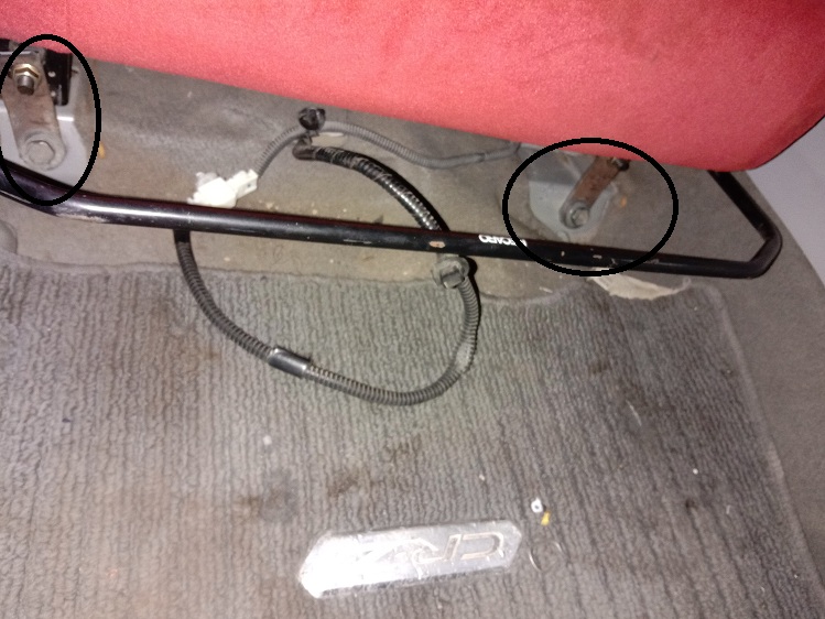
Axles, halfshaft,Shifters and calble, engine swap and fuel lines and their adapter sizes, some wiring Page 6
Exhaust and gearbox modification Page7
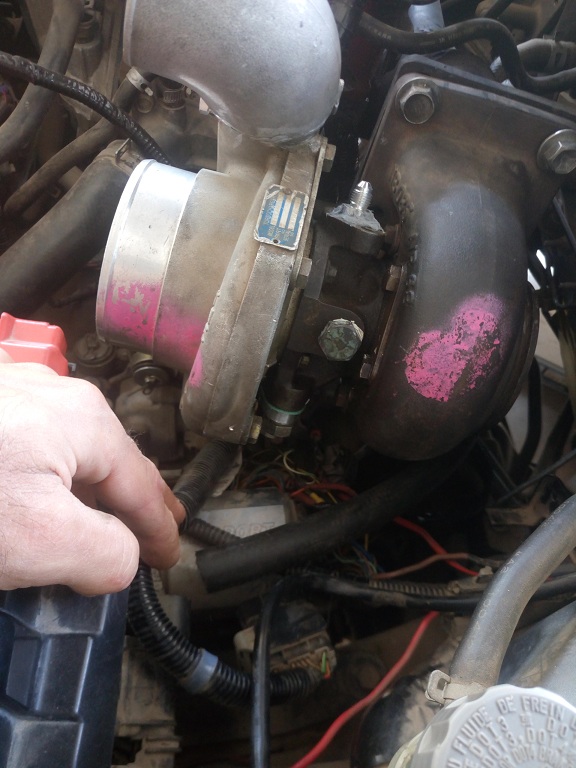
Turbo k24 Sidewinder CRZ build Page 7 & 8
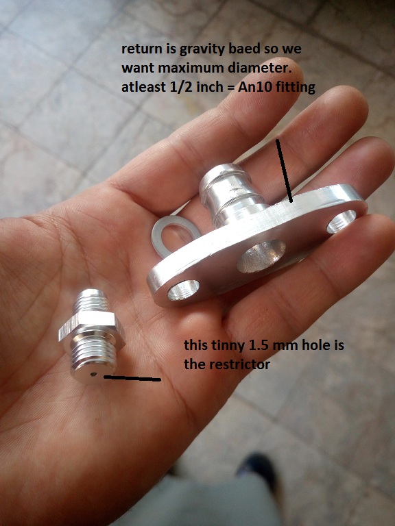
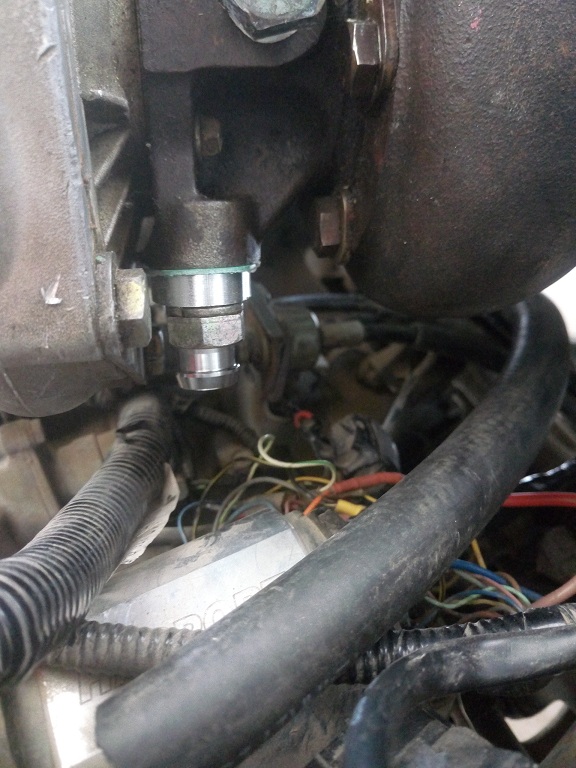
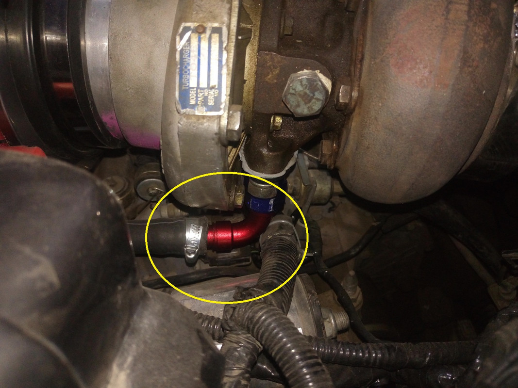
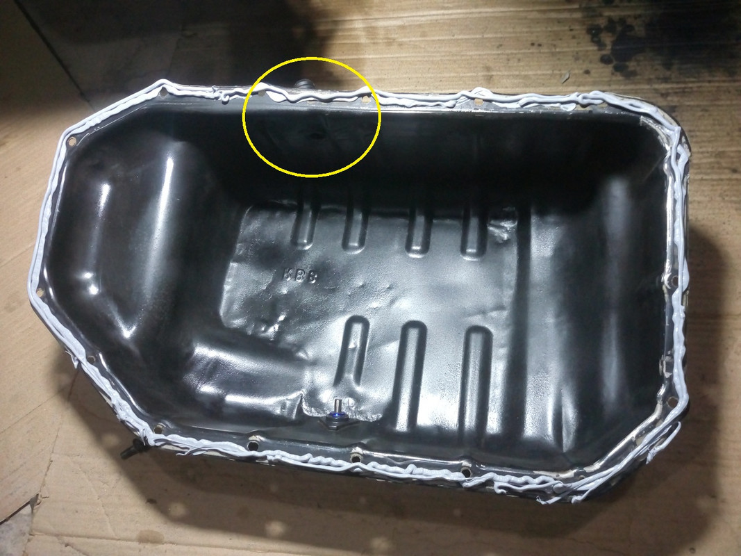
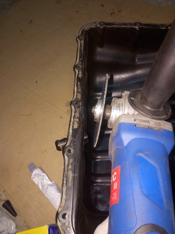
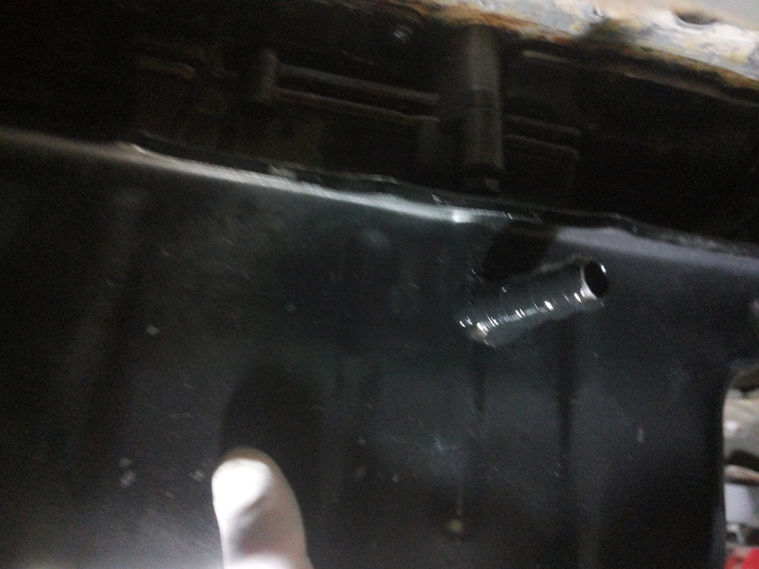
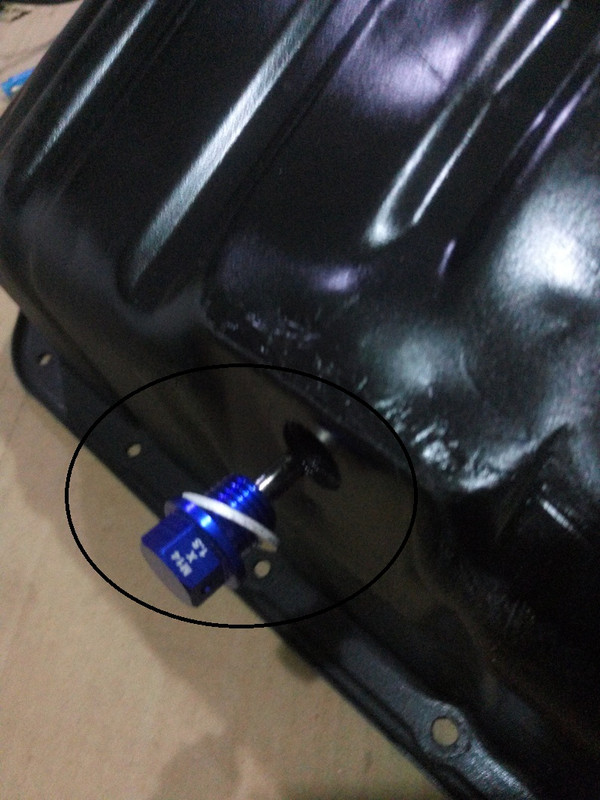
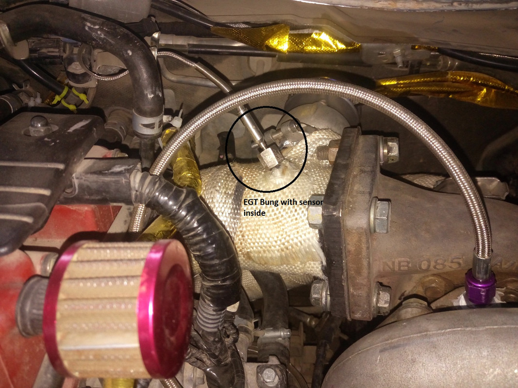
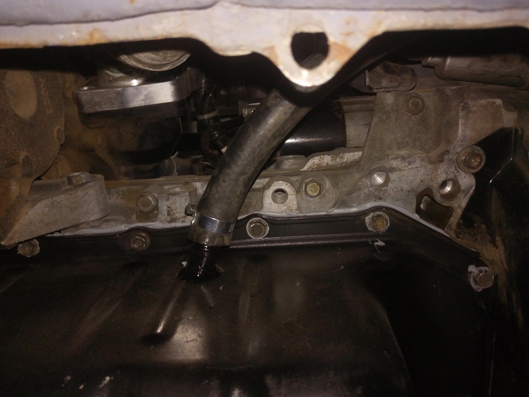
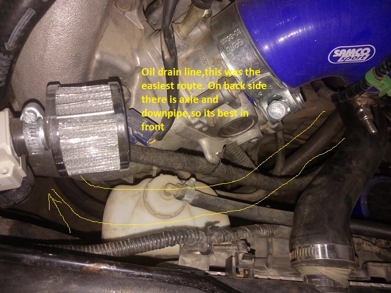
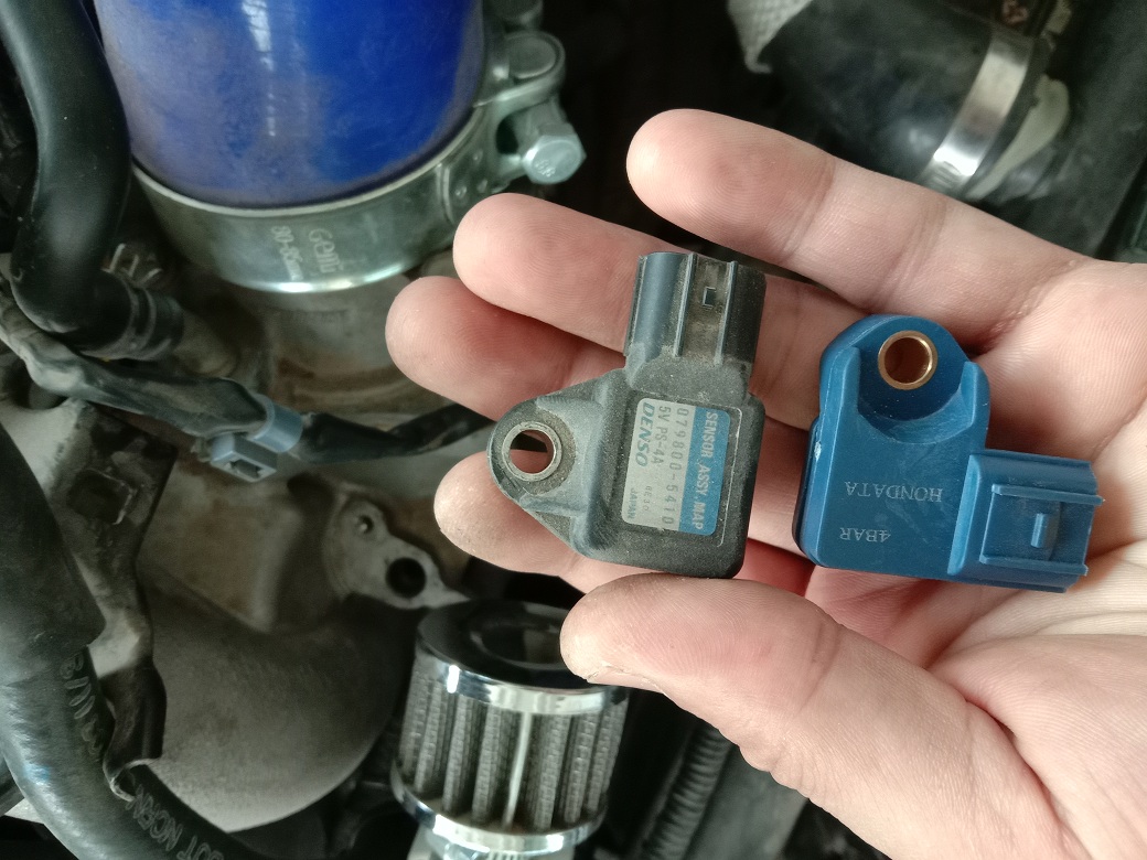
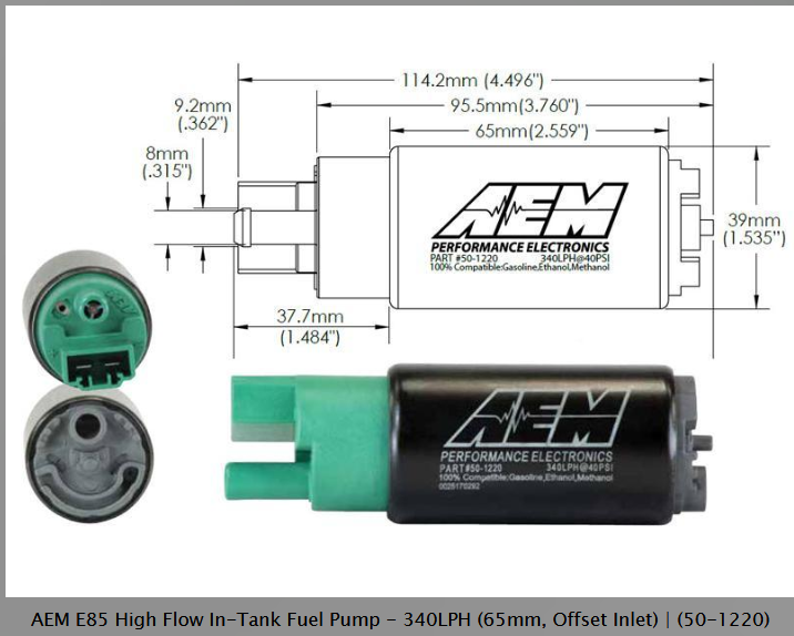
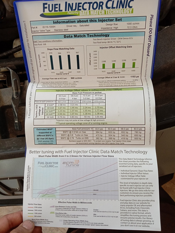
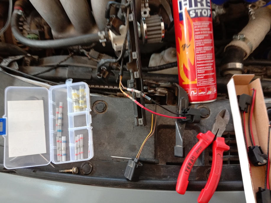
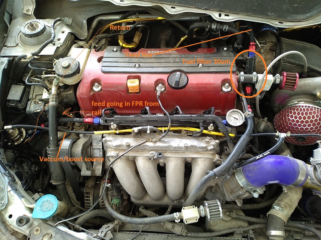
Page 9: Turbo feed,retun,oil pan modification,fuel pump,fuel injecotrs(FIC 1000cc)
Page 10 The Return Fuel setup,FPR and Fuel Lines
I also have updated Dropbox folder regarding all the offline save of this build upto page 7 of this build.I advise download and save a copy of that becasue some time pictures get deleted from hosting sites.
Dropbox folder
Diagrams and pics
Select option 'Download" on top right corner and it will download as a Zip file.extract and open.its 128 mb download uptill now.
For motivation i have made a collection of videos.Enjoy")
Now presenting the Complete K-Swap guide in video series.
All the routes,k24 or k20 in a Honda CR-Z Zf1 chassis aswell as Zf2
Honda Fit Hybrid,Honda Fit GE,Fit GK or in modern Honda.
Save the money and labour.Learn to do it with yourself.
Until recently ( Nov 18,2017) HAsport only made mounts of K-swap(k20 only) for either Civic Si(k20z3) transmissions or DC5 ones which added to swap cost as they are very expensive. If you were to use a k24 block, you would still need a k20z3 or a K20 DC5/RSX-S transmissions. But now HAsport makes mounts for CRZ which support k24 transmissions (TSX 6 spd, Civic si 2012-2015).So now a complete k24 swap can be done in very less $$$$
Now presenting the video series which contains many new things,covers both k24 & k20 route.Also covers Zf1 & Zf2 aswell as Fit GE(2nd Gen) and Fit GK(3rd Gen).
Complete k swap guide part1
Costs:
Engine k24a2/a3 with 6 spd manual transmission 1500$-2000$
Shifter & cables= 150$ https://www.ebay.com/itm/2006-Honda-Civic-Si-Shifter-And-Shifter-Cables-OEM-K20z3-/282665373668?fits=Make:Honda|Model:Civic&hash=item41d02b4fe4:g:GeEAAOSwYyxZf5NL
HAsport Mounts for k24 (now they make them) 700$ (You have to mention k24 and its transmission type when placing order)
Flashpro/Ktuner: 700$/450$
Axles: 500$(HAsport crz for k24, tell them to ship the k24 ones as the k24 half shaft is longer than k20 )
Or you can buy Insane shaft axles which are rated for 500 hp ,I contacted them and they got data of axles from Hasport (Thanks Brian for sharing data for our sake).So now you can get those in 350$ instead of HAsport 500$ and more strong also than HAsport.
It has come into my information that stock k20z half shaft and axles are bolt ons. This engine comes in Civic Fd1(Malaysia) or you can search which alternate version internationally.
I have tried Insaneshaft axles in my Fit and both axles did't fit. So kindly contact Insaneshafts before buying that if axles dont fit they will return them back and refund you.
K20 idler pulley optional: 40$(If k24 have hydraulic Power Steering pump pulley and you don’t want to use that, just disconnected the hydraulic PS lines but keep the pump and pulley there for belt sake, will save you Idler pulley as well as new serpentine belt cost)).but will require a slight modification in power steering pump so that it doesn’t get jammed running without any oil in it.
Civic Si wiring: 120$
Si ECU+ Ignition key Optional =190$( not needed if you can tow your car to Honda dealership and match the new ECU with your old CRZ keys
Custom 2-2.5” exhaust=??
Headers OEM k24
Civic Si primary O2 sensor(Or you can use CRZ one,Yes it was done in a swap in Zf2 chassis in Malaysia and it worked) =120$
Secondary o2 sensor=Optional.
Radiator OEM (its more than enough, we have three k20,s and two 24 running with OEM crz radiators and are just fine, temperature remains 90-94 C.
Misc=IAT sensor, wiring grips (If you don’t want to use your Crz one’s)=50$,coolant 4L,oil etc
Spark plugs can use the ones that come with engine(k24 or k20,BKR7EIX) but I advise new: 35$
Tune: you can use any base TSX/Si map given in Flashpro calibrations
Honda dealership matching of your new immobilizer key and civic Si ecu=50$ ?
Intake: Can use that comes with new engine or just a short ram with K&N filter =50$
Cost:4600$
Swap shop labor if you don’t have engine stand=? 400-500$ ??(shops here cost 120$ for whole engine swap)
The purpose of this thread is to do almost all work as D.I.Y and at end if you don’t have engine stand to put the engine in/out than you can go to a shop to put engine in just in few hours.
As labor is not so cheap in some countries and they cost per hour bases, so purpose of this build is to get most work done before going to workshop for final engine swap.
Some of you may know me for my Honda Fit Hybrid k20 swap.
Here it is.
It had same LEA Mf6 engine of a CRZ and the wiring of it was copied from a k20 swap crz but was never documented in detail. To date the wiring of CRZ k20 is difficult but it is about to become real easy.
In Pakistan first k20 Crz wiring was done by electrician M.Anwar in 2013. It took him near 2 months to do so as at that time very little support was there about the swaps in modern OBDII cars, yet a hybrid. The fist CRZ was done using two ecu method. The OEM k20a ecu using kpro and a crz ecu.
2nd crz was done by using single ecu of Civic Si USA(2007-11). This method is superior as it has functional OBDII port and the gauge cluster, ABS etc works. Still no documentation was done.
3rd was my car.
here is the thread about its swap
Although I wanted to document the wiring in detail in that build but I failed to do so because it was really complex and i was a beginner in this field.
At that time I promised to myself that I will document it so that its easy enough to do as D.I.Y and the one doing swap is prepared for what is required and what problems he will/might face, like AC compressor hitting chassis and break booster hitting the engine, Radiator fans hitting the intake manifold etc. If you have an automatic CRZ than don’t worry either because I will document all the method from CVT to a manual conversion and it very easy because even in a manual crz you will have to use the new shifter of civic si/tsx and cables. so only thing remains for a cvt is to add a used clutch paddle from a Honda CRZ/Fit/jazz/City/Civic along with its respective cylinder. Conversion will not cost more than 200-300$.
So with no further delay lets start
In the name of Allah, the Most Gracious, the Most Merciful
English is not my language so I apologize for any spelling and grammar mistakes.
Special thanks to Mr.Anwar and Ustad Danish who helped me when I needed.
Here is crz I bought recently for the project. Its a 2010 MT.
Here is the k24 engine for swap

This thread will mainly focus on doing all the work prior to engine installation into engine bay. Goal is to swap k20/24 in just few hours.
There are some sensor grips and main wiring grip you need to buy. Its better if you have a junk yard nearby. If you want to use a k24, than you will have to change oil pressure sending unit, Knock sensor grip, Crank sensor grip.(All these can be used of your Crz engine, but if you plan to return your crz to stock in future and don’t want to use any of its parts than you will have to find these from a junkyard or ebay etc). You will need IAT sensor and its grip.(The crz uses MAF sensor which has IAT sensor integrated into it ,so you will have to buy it, I will give its details in sensor wiring section)
As JDM models don’t have Hill assist so at this time we don’t know if it poses any problem in a k20 swap crz which has it.
I will cover each section of build separately but emphasizing most on how to do wiring on your own.
Here are the link to quick navigate to the pages..
Sensors sweap and sensors wiring connectors modification and engine preperation depending upon engine Page 1
The new forum format has changed the page numbering so much.
Break booster,oil pump,HAsport mounts and instructions Page 2
Engine preperation,clutch,flywheel installation etc etc Page 3
Alternator and starter wiring,immoblizer,pinouts etc Page 4
Main wiring,vss wiring,O2 sensor wiring etc etc Page 5
Axles, halfshaft,Shifters and calble, engine swap and fuel lines and their adapter sizes, some wiring Page 6
Exhaust and gearbox modification Page7
Turbo k24 Sidewinder CRZ build Page 7 & 8
Page 9: Turbo feed,retun,oil pan modification,fuel pump,fuel injecotrs(FIC 1000cc)
Page 10 The Return Fuel setup,FPR and Fuel Lines
I also have updated Dropbox folder regarding all the offline save of this build upto page 7 of this build.I advise download and save a copy of that becasue some time pictures get deleted from hosting sites.
Dropbox folder
Diagrams and pics
Select option 'Download" on top right corner and it will download as a Zip file.extract and open.its 128 mb download uptill now.
For motivation i have made a collection of videos.Enjoy
All the routes,k24 or k20 in a Honda CR-Z Zf1 chassis aswell as Zf2
Honda Fit Hybrid,Honda Fit GE,Fit GK or in modern Honda.
Save the money and labour.Learn to do it with yourself.